Brakes - Alternate Brake Valves / Controller
Aim - this section provides an overview of the typical operation of the drivers valves for the Westinghouse air brake system, and describes the "best" brake controller settings for Open Rails (OR) ENG files.
If you wish to provide any feedback on this page, please use the contact page. It would br great to have some feedback as this helps to ensure the accuracy of the information and models.
Index
Sample Brake Code - 26-L Brake Control Valve
Westinghouse 24-RL Brake Valve
Sample Brake Code - 24-RL Brake Control Valve
Introduction
known.
Westinghouse 26-L Brake Valve
This information has been extracted from various Westinghouse publications, some of which may be found in the Useful References. Whilst a few different styles and types have been used, the following information should apply in general and give a reasonably close approximation of its operation.
The operating positions of the 26L brake valve are shown in the diagrams below. The Automatic brake valve (Train brake) is shown on the left hand side of the diagram, whilst the Independent brake valve (Engine Brake) is shown on the right side of the respective diagrams.
 26-L Brake Valve.
Automatic brake valve (Train Brake)
The automatic brake valve, which controlled the train brakes has 6 positions of operation as follows:
- Release - In this position the brake valve releases the train brakes, and recharges the brake system (auxilary reservoirs, etc) on the train.
- Minimum reduction - When the brake handle is move to this position, a pressure reduction of approximately 6-8 psi occurs in the brake pipe, and minimum braking effort is applied.
- Service - In moving the handle from left to right through the service zone, the degree of braking effort is increased until, with the handle at the extreme right if this sector, the handle is in full service position, and full service braking effort is obtained, by reducing the brake pipe pressure to between 23 - 26 psi.
- Suppression - In this position the train brake system provides a full service application, it will also recover a penalty brake application.
- Handle off - In this position, the equalizing reservoir will be reduced to zero and the brake pipe will be reduced to ten pounds pressure.This is the position in which the handle must be placed on trailing units of a multiple-unit locomotive or on locomotives being towed 'dead' in a train.
- Emergency - In this position, the air in the brake pipe is exhausted to atmosphere to cause a heavy reduction in brake pipe air pressure, resulting a heavy brake application.
Independent brake valve (Engine Brake)
The independent brake valve, which controlled the engine has 2 positions of operation as follows:
- Release - This position releases the locomotive brakes, provided the automatic brake handle is in the release position.
- Full Application - This position is located with handle at the extreme right of the quadrant. In moving the handle from left to right through the service zone the degree of locomotive braking effort is increased until full application braking effort is obtained.
Bailing off - depressing the independent brake valve handle in any position will result in releasing all locomotive brake cylinder pressure developed as a result of a brake pipe reduction or an automatic brake application. Depression of the independent brake handle whenever the handle is in the release position will cause the release of any automatic brake application existing on the locomotive. When an automatic brake application is made, the independent brake must be bailed off for 4 seconds per locomotive in the consist AND until the brake pipe air quits exhausting.
Sample Brake Code - 26-L Brake Control Valve
The brake configuration on this page represents the brake configuration generally used to achieve a reasonable performance in Open Rails. Some of the functionality described in the brake control may not be currently set up in Open Rails.
This section of code describes the 26-L controller (brake valves) in the locomotive. This configuration has not been personally tested by me, so any feedback is welcomed.
Comment ( *** Brake control equipment *** )
Comment ( *** Engine Brake (Independent) *** )
Brake_Engine ( 0 0.56 0.025 0.56
NumNotches ( 2
Notch ( 0.000 0 EngineBrakesControllerReleaseStart )
Notch ( 0.012 1 EngineBrakesControllerApplyStart )
)
)
Comment ( *** Train Brake (Automatic) *** )
Brake_Train ( 0 2.5 0.025 0.135
NumNotches ( 7
Notch ( 0 0 TrainBrakesControllerReleaseStart )
Notch ( 0.135 0 TrainBrakesControllerMinimalReductionStart )
Notch ( 0.136 1 TrainBrakesControllerGraduatedSelfLapLimitedHoldingStart )
Notch ( 0.715 0 TrainBrakesControllerFullServiceStart )
Notch ( 0.716 0 TrainBrakesControllerSuppressionStart )
Notch ( 0.717 0 TrainBrakesControllerNeutralHandleOffStart )
Notch ( 2.50 0 TrainBrakesControllerEmergencyStart )
)
)
Brake_Hand ( 0 1 0.0125 0 Comment ( Note: some locomotives were not fitted with handbrakes. )
NumNotches( 0 )
)
Make sure that you test your settings with the brake tests described on the testing page.
Westinghouse 24-RL Brake Valve
This information has been extracted from various Westinghouse publications, some of which may be found in the Useful References. Whilst a few different styles and types have been used, the following information should apply in general and give a reasonably close approximation of its operation.
The operating positions of the 24-RL brake valve are shown in the diagrams below. The Automatic brake valve (Train brake) is shown on the left hand side of the diagram, whilst the Independent brake valve (Engine Brake) is shown on the right side of the respective diagrams.
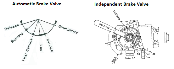 24-RL Brake Valve.
Automatic brake valve (Train Brake)
The automatic brake valve, which controlled the train brakes has 6 positions of operation as follows:
- Release - In this position the brake valve releases the train brakes, and recharges the brake system (auxilary reservoirs, etc) on the train.
- Running - Recharges the brake system (auxilary reservoirs, etc) on the train. The brake valve must be placed in this position when the locomotive is cut out.
- First Service - Reduces equalizing reservoir pressure by 6 to 8 PSI at a service rate. Leaving the handle in this position will result in continued equalizing reservoir reduction at a slower rate. When the first service cut-out cock is cut out, this position becomes another LAP position.
- Lap - Prevents air from entering or leaving brake pipe at the brake valve, which holds a brake application applied. This position is also used to reset the brake equipment after a penalty or an emergency application.
- Service - Reduces brake pipe pressure at a service rate as long as the brake valve is in this position. The brake valve must be placed in LAP position to stop the reduction of equalizing reservoir pressure.
- Emergency - Causes an emergency application of air brakes regardless of whether the brake valve is cut in or cut out.
Independent brake valve (Engine Brake)
The independent brake valve, which controlled the engine has 2 positions of operation as follows:
- Release - This position releases the locomotive brakes, provided the automatic brake handle is in the release position.
- Full Application - This position is located with handle at the extreme right of the quadrant. In moving the handle from left to right through the service zone the degree of locomotive braking effort is increased until full application braking effort is obtained.
Bailing off (or Actuate) - depressing the independent brake valve handle in any position will result in releasing all locomotive brake cylinder pressure developed as a result of a brake pipe reduction or an automatic brake application. Depression of the independent brake handle whenever the handle is in the release position will cause the release of any automatic brake application existing on the locomotive. When an automatic brake application is made, the independent brake must be bailed off for 4 seconds per locomotive in the consist AND until the brake pipe air quits exhausting.
Sample Brake Code - 24-RL Brake Control Valve
The brake configuration on this page represents the brake configuration generally used to achieve a reasonable performance in Open Rails. Some of the functionality described in the brake control may not be currently set up in Open Rails.
This type of code configures the 24-RL controller (brake valves) in the locomotive. This configuration has not been personally tested by me, so any feedback is welcomed.
Comment ( *** Brake control equipment *** )
Comment ( *** Engine Brake (Independent) *** )
Brake_Engine ( 0 0.56 0.025 0.56
NumNotches ( 2
Notch ( 0.000 0 EngineBrakesControllerReleaseStart )
Notch ( 0.012 1 EngineBrakesControllerApplyStart )
)
)
Comment ( *** Train Brake (Automatic) *** )
Brake_Train ( 0 1 0.0125 0.6
NumNotches ( 6
Notch( 0 0 TrainBrakesControllerReleaseStart )
Notch( 0.2 0 TrainBrakesControllerRunningStart )
Notch( 0.4 0 TrainBrakesControllerMinimalReductionStart )
Notch( 0.6 0 TrainBrakesControllerGraduatedSelfLapLimitedStart )
Notch( 0.8 0 TrainBrakesControllerContinuousServiceStart )
Notch( 1 0 TrainBrakesControllerEmergencyStart )
)
)
Brake_Hand ( 0 1 0.0125 0 Comment ( Note: Most locomotives were not fitted with handbrakes. )
NumNotches( 0 )
)
Make sure that you test your settings with the brake tests described on the testing page.
Dynamic Brake Controller
The electric motors on a locomotive can be switched from a motor tytpe function to a generator type function. By doing this a "load" can be placed on the motor which then acts as a retarding force on the rotation of the motors shaft, and hence the rotation of the locomotives wheels. This load can either be in the form a series of resistors which are switched across the supply terminals of the motor (Resistive braking), or by feeding the generated output of the motor back into the electrical supply network (Regenerative braking). Resistive braking tends to be more common on diesel locomotives, and as this type of braking generates large amounts of heat in the resistors, fans are often required to assist with the dissapation of heat.
Normally the use of the dynamic and pneumatic braking are not used at the same time, unless the locomotive driver is switching from one form of braking to another.
Typically the dynamic brake handle is located near the throttle handle. The brake handle has two positions; OFF and SETUP, and an operating range of 1 through 8 (FULL), through which the handle moves freely without notching. Mechanical interlocking prevents the dynamic brake handle from being moved out of the OFF position unless the throttle is in IDLE and the reverser is positioned either forward or reverse operation.
CAUTION - During transfer from power operation to dynamic braking, the throttle must be held in IDLE for at least 10 seconds before moving the dynamic brake handle to the SET UP position. This is to eliminate the possibility of a sudden surge of braking effort with possible train run-in or traction motor flash-over.