Couplers
Aim - this section provides an overview of couplers, and seeks to describe an "optimal" coupler setting based upon the current setup for Open Rails (OR)
If you wish to provide any feedback on this page, please use the contact page. It would br great to have some feedback as this helps to ensure the accuracy of the information and models.
Index
Sample code for Advanced Coupler
Introduction
Over the years, with the development of railways, a number of different types of couplers have been used to connect adjoining wagons together. The equipment that connects the couplings to the rolling stock is known as the draft gear or draw gear.
The majority of the coupler types allow a certain amount of slack to occur between wagons. So in railway terms, slack action, is the amount of free movement of one car before it transmits its motion to an adjoining coupled car. Some amount of slack is required in the coupling to allow the coupling to be flexible enough to go around curves on the railway. Slack can also be very helpful in starting a train. If the train is stetched then the locomotive needs to pull the full load of the train at once, and if the train has a high starting resistance, then the locomotive may not have sufficient power to start. To overcome this the train can be 'bunched' up, and thus when the train starts the locomotive is only starting one car at a time until the slack is taken out of the coupling system, thus the starting resistance of the train is substantialy reduced as the cars start to move. Slack can also work against the train driver as it allows individual cars to move independently of each other, and thus they can end up travelling at different speeds to each other.
If the speed difference is high enough between individual cars, then the forces produced in the coupler between adjoing cars maybe high enough to break the coupler. Hence slack is also used to protect the rolling stock, from damaged coupler or dmamage to the cars themselves under the influence of shocks and jerks (dynamic forces) that occur during the movement of the train: the elastic elements in the couplers absorb some of the energy and smooth out sudden changes in speed.

The action of the various types of couplers can be described on a Force vs Displacement diagram as shown in the two example figures, above which are described more fully in the he article Simulated comparisons of wagon coupler systems in heavy haul trains. The diagram on the left is for an older style Draw Hook and Buffer connection, whereas the diagram on the right is from a more modern Auto coupler connection. The Auto Coupler presents a more symmetrical graph as it has similar characteristics regardless of whether the coupler in in tension (pulling) or compression (pushing). The Draw Hook and Buffer connection is more asymmetrical in appearance as when the coupling is in tension (pulling) the Draw Hook is more rigid, and has less slack then an Auto Coupler, wheereas when it is in compression (pushing) the Buffers tend to have a more cushioned effect similar to an Auto Coupler.
Open Rails uses this type of approach to define how the coupler responds during train movements. Two options are provided in OR, a 'Simple' version which is the original OR version, and an 'Advanced' version. The setting of the Advanced version is described below, and the Simple version should be the same as it has always been.
Advanced Coupler
The Advanced coupler feature simulates the impact of coupler slack operation on trains.
The Advanced Coupler is modelled on a three zone displacement model as described in the following diagram.
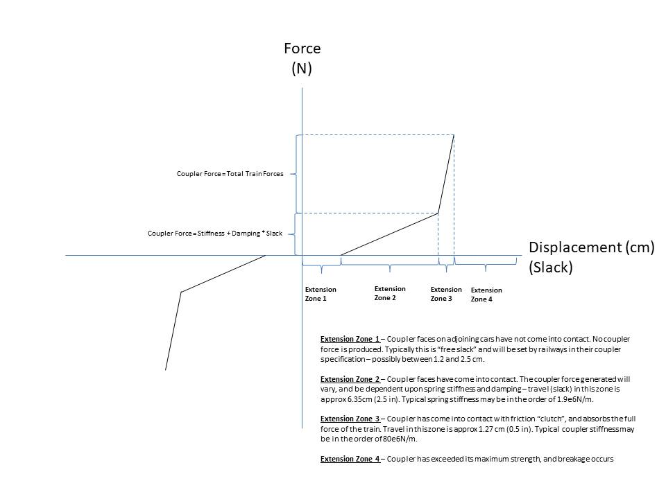
Thus to specify a coupler it is necessary to describe the displacement distances for each zone, as well as the applicable forces at these points. Also as the coupler can have different characteristics depending upon whether it is tension or compression, each of these different areas need to also be specified.
OR typically models the coupler based upon the coupler defined for the rear of the car, and it is assumed that the coupler on the front of the following car is the same type, and hence, coupler slack between the two cars will be double (2x) the value specified in the following coupling definition statements.
Advanced coupler functionality will only be added if the following parameters are applied to the
The parameters required to specify the coupler in accordance with the above diagram are as follows:
Note: All values should be +ve equivalent (including compression values as OR adjusts them as appropriate).
Sometimes the amount of coupler slack applied to each coupler may be sufficient to cause the couplers to appear to have an "air gap" between them, thus when setting up the slack in the wagon it is suggested that the coupler animation feature should be used where the slack movement between cars is sufficient to make this gap appear between the couplers.
A sample code for specifying a coupler is provided in the Sample code for Advanced Coupler section. To see how the Advanced Coupler performs, and for a working code copy, look at the relevant Demonstration Activity.
To view the coupler forces and other coupler related paramter performance in Open Rails, refer to the extended HUD, FORCES INFORMATION by pressing the
Coupler Animation
The coupler animation feature models a coupler which will move as the train slack increases and decreases, and also rotates the coupler as it moves through a curve. Also it is possible for air hoses to be positioned between cars and have them move as train slack varies. These feature are mutually exclusive, so they can be implemented individually if desired.
The shape reference points for both the coupler and air hose shapes should be the point where they connect together.
The parameters required to enable coupler animation are as follows:
where name = coupler shape file, x = distance left or right of track centre, y = height of coupler above track, and z = coupler position from car along centre line of track.
where name = coupler shape file, x = distance left or right of track centre, y = height of coupler above track, and z = coupler position from car along centre line of track.
where name = coupler shape file, x = distance left or right of track centre, y = height of coupler above track, and z = coupler position from car along centre line of track.
where name = coupler shape file, x = distance left or right of track centre, y = height of coupler above track, and z = coupler position from car along centre line of track.
The parameters required to enable air hose animation are as follows:
where name = air hose shape file, x = distance left or right of track centre, y = height of air hose above track, and z = air hose position from car along centre line of track.
where name = air hose shape file, x = distance left or right of track centre, y = height of air hose above track, and z = air hose position from car along centre line of track.
where name = air hose shape file, x = distance left or right of track centre, y = height of air hose above track, and z = air hose position from car along centre line of track.
where name = air hose shape file, x = distance left or right of track centre, y = height of air hose above track, and z = air hose position from car along centre line of track.
Open Rails will use some calculated defaults to render both of the above features, however additional accuracy can be achieved if modelers add the following parameters to the wagon section of their
The movement of the air hose is calculated based upon the distances shown in the following diagram.
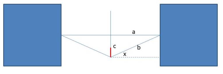
Where:
a = Air hose position (varies in game as conditions change) =
b =
c = the calculated distance that the air hose connection will move upwards (or downwards).
NB: Each parameter above only refers to the car that it is "included in", hence when each car is coupled together, the parameters from the preceeding and following car will be added together to approximate the total "coupled" distance between cars.
Coupler Breaking Force
If the force on the coupler exceeds this force then the coupler will break (requires "Break" option to be selected in OR Option Menu). Typically the couplers have a lower mechanical strength and will break before the cars are damaged due to excessive forces. The force on each of the couplers in the train can be identified in the extended HUD. The coupler force will vary depending upon the number of wagons connected to the coupler, ie the load, and will also vary as the train negiotiates hills or curves, etc which increase the load force. In driving the train the driver needs to be conscious of not putting excessive loads (forces) on the coupler.
For NSW operational practice, typical coupler breaking forces (or Draw Capacity) are somewhere between 0.15MN (150kN) and 4.45MN (4500kN), as summarised in the table below, which shows a selection of the wagons, and locomotives from the documents in the Useful Links section below. Refer to the Draw Capacity column. Similarly values for UK practice are shown in one of the other document, including screw and draw hook couplings.
Coupler Type |
Draw Capacity (MN) |
Comments |
|---|---|---|
Coal wagons - modern permanently coupled (Eg PHEH) |
2.45 |
Bar type connection |
Coal wagons - bogie (Eg BCH) |
0.75 |
autocoupler, metal body |
Water Gin (Eg L229) |
0.50 |
|
Rail Car - Modern style (Eg XPT) |
0.25 |
|
Diesel - Modern (Eg 5000 Class) |
4.45 |
Special coal haulage locomotive |
Diesel - Branch Line (Eg 48 Class) |
0.90 |
Autocoupler |
Diesel - Mainline (Eg 442 Class) |
1.80 |
Autocoupler |
Passenger - Modern style (Eg ARL) |
0.89 |
Steel body |
Passenger - Modern style (Eg SBN) |
0.50 |
Steel body |
Passenger - Older style (Eg FO) |
0.15 |
Wooden body |
Steam locomotive - Modern (Eg 3801) |
0.90 |
|
Steam locomotive - Older style (Eg 2705) |
0.75 |
|
Sample Code for Advanced Coupler
The following code sample has been set up to match the Miner M-901E Draft Gear. This would simulate a coupler of the type shown in the RHS of the diagram in the Introduction section above. Similarly a Hook and Chain model should be able to be modelled if the correct slack and force values are entered. A Bar type coupler would be set by setting the
Typically the lines shown in red text are the only ones that would need to be changed on individual wagons.
Comment ( Open Rails Advanced Coupler )
Coupling (
FrontCouplerAnim ( CouplerA.s 0.0 0.9 -0.35 )
RearCouplerAnim ( CouplerB.s 0.0 0.9 -0.35 )
Spring (
ORTSTensionStiffness ( 50000lbf 511000lbf )
ORTSTensionR0 ( 0in 1.0in )
ORTSTensionSlack ( 2.75in 0.4in )
ORTSCompressionStiffness ( 50000lbf 511000lbf )
ORTSCompressionR0 ( 0in 1.0in )
ORTSCompressionSlack ( 2.75in 0.4in )
ORTSBreak ( 1.8e6N 511000lbf )
)
CouplingHasRigidConnection ( 0 )
)
Force Conversion
Convert long Tons (UK) force to Newtons.
tonsf (UK) to N:
Useful References
NSW Locomotive and Rolling Stock Data
The Evolving Coal Wagon by Ross Peter Golotta
Structural Requirements for Drawgear and Buffers on Railway Vehicles (Superseded UK standard)