Steam Locomotive - Extended (Debug) HUD
Aim - To describe the information found on the extended heads up display (HUD) for a steam locomotive in Open Rails.
If you wish to provide any feedback on this page, please use the contact page. It would be great to have some feedback as this helps to ensure the accuracy of the information and models.
Index
Introduction
In relation to the driving of a steam locomotive, the heads up display (HUD) provides information for the locomotive driver that assists them in determining the current state and performance of the locomotive. There are two HUD types in Open Rails, the main HUD which provides sufficient information on the current status of the locomotive for the purpose of driving the locomotive, and the extended steam HUD which provides more detailed information which is primarily desgined for advanced users to configure a locomotive or debug performance issues. For information on the main HUD refer to the Open Rails manual. The information and significance of the detail on the extended steam locomotive HUD will be described below.
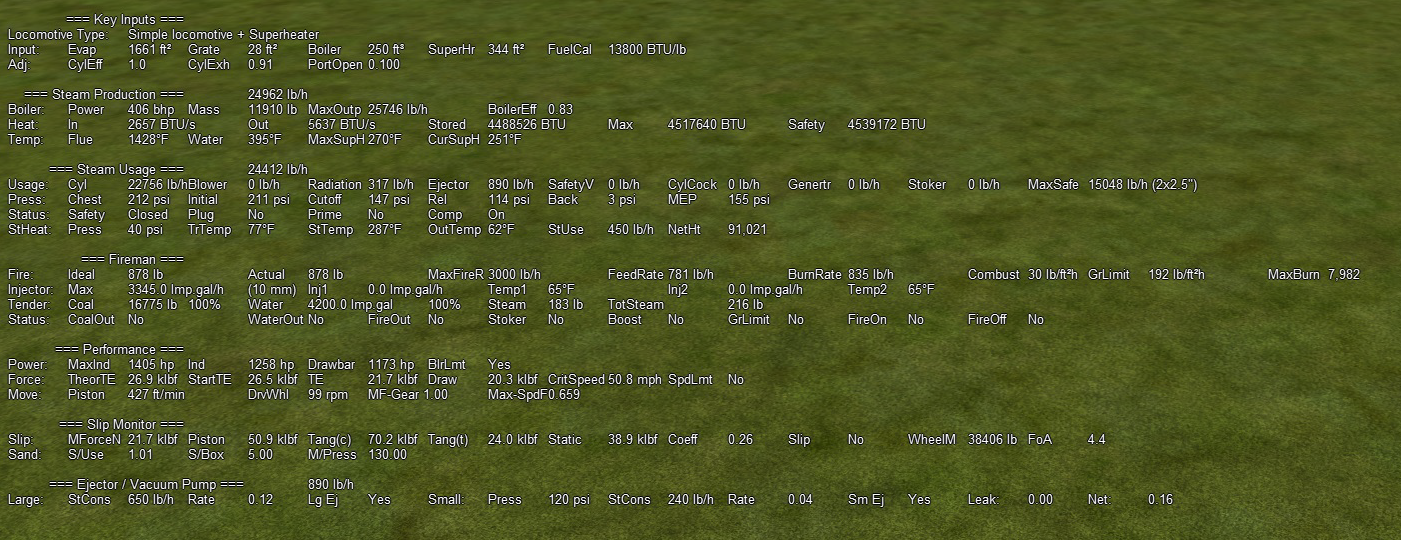
The extended steam HUD can be accessed, once the main HUD is visible, pressing "Shft F5" a number of times until it appears. It will look like the picture below.
Key Inputs
Provides information of the key input parameters read from the ENG file.
Line 1 - Locomotive Type
This line describes the type of steam locomotive that Open Rails has loaded. The type of locomotive is based upon user defined ENG file parameters, if these are not present in the ENG file, OR will make assumptiuons in regard to the type of locomotive.
Line 2 - Input
This line provides information related to the key inputs used to define the locomotive, and will confirm the values that Open Rails is using.
They are from left to right:
- Evap - the evaporation area in sq ft. This will determine the effectiveness of steam production.
- Grate - the grate area of the firebox.
- Boil - Boiler - the volume of the boiler. If this value is too small, then the ability to maintain water levels might be an issue.
- Sup - Superheater Area - size of the superheater element.
- FuelCal - Fuel calorific.
Line 3 - Adj (Adjustments)
This line provides information related to some of the values assigned to "ADVANCED" physics parameters.
They are from left to right:
- CylEff - the cylinder efficiency.
- CylExh - the fraction of the cycle at which the exhaust valve opens.
- PortOpen - size of the cylinder port opening.
Steam Production
Provides information related to the production of steam within the locomotive. The figure shown level with the steam production heading is the total current steam generation rate by the boiler. If this value is exceeded by the steam usage rate for long periods, then steam pressure will drop in the locomotive.
Line 1 - Boiler
This line provides information related to the boiler.
They are from left to right:
- Power - the calculated current power of the boiler.
- Mass - the current mass of water in the boiler.
- Out - the maximum estimated steam generation rate. (Can be adjusted as an ADVANCED parameter)
- BoilerEff - current boiler efficiency factor (between 0.0 - 1.0). (Can be adjusted as an ADVANCED parameter)
Line 2 - Heat
This line provides information related to the boiler heat.
They are from left to right:
- In - the amount of heat being added to the boiler, due to burning of fuel.
- Out - the amount of heat being taken from the boiler, due to usage of steam.
- Stored - the current total (nett) heat in the boiler. Ideally this should be maintained below the value in the Max or Safety HUD parameters.
- Max - the maximum calculated heat in the boiler at the maximum working pressure of the boiler.
- Safety - the maximum calculated heat in the boiler when the safety values release. If the stored heat exceeds this value when in manual firing mode, then the safety valves will operate.
Line 3 - Temp
This line provides related to the working temperatures of the boiler.
They are from left to right:
- Flue - the flue temperature.
- Water - the water temperature (Water Temp impacts the value of the Boiler Pressure).
- MaxSupH - the maximum superheat temperature that the locomotive will operate at. (Can be adjusted as an ADVANCED parameter)
- CurSupH - the current superheat temperature of the locomotive.
Steam Usage
Provides information related to the usage of the steam within the locomotive. The figure shown level with the steam usage heading is the summed total steam usage due to all steam operated devices on the locomotive.
Line 1 - Usage
This line provides the actual steam usage figures in lbs/h for the various devices that use steam.
They are from left to right:
- Cyl - steam cylinder - usage will increase dependent upon speed of the locomotive and cutoff (reverser).
- Blower - Blower - typically only used when the locomotive is stationary (usually only operational in Manual Firing mode).
- Radiation - Radiation loss - Equivalent loss of heat due to radiation from boiler - a constant value.
- Ejector - Steam Ejector - steam usage (Typically usage will only appear on locomotives with vacuum braking).
- Comprsr - Air compressor - steam usage (Typically usage will only appear on locomotives with air braking).
- SafetyV - Safety valve - Steam exhausted through the safety valves - only occurs when in manual firing mode, and will be dependent upon the assessed number of valves venting and their size.
- CylCock - Cylinder cock - Steam escaping from the cylinder cock.
- Genertr - Generator - steam usage for generate used to produce electricity for lighting, etc.
- Stoke - Mechanical Stoker - Steam used by the mechanical stoker - only occurs when a mechanical stoker fitted.
- MaxSafe - Safety Valves Installed - shows the maximum possible amount of steam exhaust that can be released to the air if the steam safety valves "let go". The figures in the brackets indicate the number and size of safety valves assumed to be fitted to the locomotive.
Line 2 - Press
This line provides a view of the steam pressures associated with the operation of the locomotive. In particular, steam pressures relevant to the cylinder steam indicator drawing are shown in this line. This HUD line will change depending upon whether the locomotive is a compound locomotive, in which case two lines will be shown, one for the high pressure cylinder, and one for the low pressure cylinder. For single expansion locomotives, only one line will be shown.
Typically the values on these lines will be from left to right:
- Chest - Steam Chest is located on the inlet to the steam cylinder and this pressure indicates the maximum pressure available for the cylinder.
- Initial - Initial presseure is the pressure intially applied to the steam cylinder.
- Cutoff - Cutoff pressure is the pressure when the inlet valve to the cylinder cloese and steam input to the cylinder is "cutoff".
- Rel - Release pressure is when the exhaust valve is opened to allow steam to leave the steam cylinder.
- Back - Back pressure is the residual pressure in the cylinder once the steam piston commences its return stroke.
- MEP - Mean Effective Pressure - is the mean pressure calculated across the complete piston cycle. It is used to calculate the tractve force of the locomotive.
Line 3 - Status
This line provides the status of various steam usage events.
They are from left to right:
- Safety - Safety valve - Indicates whether the safety valve is open and releasing steam, or whether it is closed.
- Plug - Fusible Plug - was a safety device fitted to the boiler which melted should the boiler water level get too low. Yes indicates that the plug has melted and released water and steam pressure. This will cause the boiler pressure to drop.
- Prime - Priming occurs when water rather then steam is injected into the steam cylinders, which can cause significant damage to the cylinders. Typically this is caused when the water level in the boiler get too high. Yes indicates that the boiler has primed.
- Comp - Compound valve - indicates if the compound valve has been opened or closed. When the valve is opened, the high pressure cylinder will be bypassed. This was often done when starting the locomotive. Applies only to compound locomotives.
Line 4 - StHeat
This line provides the status of steam heating provided to passenger carriages. This line will not appear if the steam heating is not fitted to the locomotive or not turned on.
They are from left to right:
- Pressure - indicates the pressure that the steam heating valve has been adjusted to.
- TrTemp - Train Temperature - indicates the current temperature inside the train, ie what the passengers are experiencing.
- StTemp - Steam Temperature - indicates the current temperature of the steam used for heating the train, this will vary with the pressure setting.
- OutTemp - Outside Temperature - indicates the current temperature outside the train. It will vary depending upon the season and world location.
- StUse - Steam Usage - indicates the current amount of steam being used to heat the train.
- NetHeat - Nett Heating - indicates the current heat loss (-) or gain (+).
Fireman
Provides information related to the fireman and how combustion is performing within the locomotive.
Line 1 - Fire
This line provides the status of various information related to the fire.
They are from left to right:
- Ideal - Ideal Fire Mass - this indicates the ideal fire mass of fuel given the size of the grate area.
- Actual - Actual Fire Mass - this is the current fuel mass. If this value is less then the ideal mass, then the fire will be "too thin" and burn too quickly, alternatively if it is higher then the ideal, the fire will be "too thick", and will burn slower as the draught will be limited due to the fire thickness.
- MaxFireR - Maximum Firing Rate - this is the maximum rate that the fireman can feed fuel onto the fire. At high speeds the fireman may find it difficult to keep fuel up to the fire.
- FeedRate - Fuel rate - indicates the current rate of fuel being added to the fire. Changes in this rate are not instantaneous, as it would take time for the fireman to adjust to altered conditions.
- BurnRate - Burn Rate - indicates the current rate at which fuel is burning in the firebox. Changes in this rate are not instantaneous, as it takes time for the fuel to burn.
- Combust - Combustion Rate - indicates the current combustion rate per the grate size.
- GrLimit - Grate Limit - indicates the grate limit of the locomotive. Once the Combustion rate reaches the grate limit no more heat can effectively transferred to the boiler. Trying to burn more fuel will not be economical.
- MaxBurn - indicates the maximum amount of fuel that can be burnt at the grate limit of the locomotive. Realistically this value may not be achieved, as a human fireman could only continuously shovel about 3,000 lb/h of coal, so values in excess of this value may not be achieveable..
Line 2 - Injector
This line provides various information on the operation of the injectors which add water to the boiler.
They are from left to right:
- Max - indicates the maximum amount of water that the injectors can inject into the boiler in an hour, and the size of the injectors selected for the locomotive are shown in brackets.
- Inj1 - Injector 1 - provides information of the amount of water and the temperature of the water flowing into the boiler. The lower the temperature of the water the more heat "lost", and required to be replaced by the fire.
- Inj2 - Injector 2 - provides information of the amount of water and the temperature of the water flowing into the boiler. The lower the temperature of the water the more heat "lost", and required to be replaced by the fire.
Line 3 - Tender
This line provides various information related to the locomotive fuel.
They are from left to right:
- Coal - indicates amount of caol remaining in the tender or coal bunker. This is shown both in terms of the actual amount of coal, and also as a percentage of the total capacity of the coal bunker.
- Water - indicates the amount of water left in the tender or water tank. This is shown both in terms of the actual amount of water, and also as a percentage of the total capacity of the water tank.
- Steam - indicates the current amount of steam being used instantaneously by the locomotive.
- TotSteam - indicates the total amount of steam used by the locomotive since the start of the activity.
Line 4 - Status
This line provides the status of various events related to the firemans performance.
They are from left to right:
- CoalOut - indicates that all the coal has been used up in the tender or coal bunker.
- WaterOut - indicates that all the water has been used up in the tender or water tank.
- FireOut - indicates that the fire has been allowed to go out.
- Stoker - indicates locomotive is fitted with a mechanical stoker.
- Boost - indicates that the fireman is in "boost" mode. Typically a single fireman could only shovel a certain amount of coal per hour. In boost mode the fireman can exceed the normal hourly rate for small periods of time, but not indefinitely.
- GrLimit - indicates that the grate limit of the locomotive has been exceeded.
- FireOn - indicates that AI fireman has been "told" to start adding fuel to the fire. This can be activated by the player, and is useful if the locomotive needs to build up heat in preparation for a uphill gradient, or when first starting.
- FireOff - indicates that AI fireman has been "told" to stop adding fuel to the fire. This can be activated by the player, and is useful if the locomotive is coming to a station, and the heat generated in the boiler needs to be reduced.
Performance
Provides information related to the performance of the locomotive, and mainly focuses on the power and forces associated with the locomotive.
Line 1 - Power
This line provides information on the power of the locomotive.
They are from left to right:
- MaxInd - Maximum Indicated Power - indicates the maximum theoretical indicated power of the locomotive. (Can be adjusted as an ADVANCED parameter)
- Ind - Indicated power - actual current indicated power that the locomotive is operating at.
- Drawbar - Drawbar power - indicates the current Drawbar power that the locomotive is operating at.
- BlrLmt - Boiler Limit - indicates whether the output power of the locomotive is limited by the boiler steam production or the power produced by the steam pistons.
Line 2 - Force
This line provides information on the relevant forces of the locomotive.
They are from left to right:
- TheorTE - Theoretical Tractive Effort - is the maximum theoretical tractive effort of the locomotive. (Based upon a factor 0f 0.85)
- StartTE - Starting Tractive Effort - is the measured tractive effort when the locomotive starts to move.
- TE - Tractive Effort - indicates the current tractive effort as the locomotive is in operation.
- Draw - Drawbar Force - indicates the current force at the drawbar as the locomotive is operating.
- CritSpeed - Critical Speed - indicates the calculated critical speed of the locomotive. This is the point where typically maximum power was produced by the locomotive, and was based upon the capabilities of the piston. Typically a saturated locomotive reached this point when the psiton was operating at 700 ft/min, and a superheated locomotive when piston speed was 1000 ft/min.
- SpdLmt - Speed Limit - indicates whether the power of the locomotive has reached its limit (ie Ind > MaxInd), in which case the locomotive will not be able to produce any more power.
Line 3 - Move
This line provides information related to the movement of the locomotive.
They are from left to right:
- Piston - Piston Speed - indicates the current speed of the steam piston.
- DrvWhl - Drivewheel Revolutions - indicates the current drivewheel revolutions.
- MF-Gear - Motive Force Gear Factor - indicates the factor used to adjust tractive effort due any gearing of the locomotive.
- Max-SpdF - Maximum Speed Factor - indicates the maximum speed factor of the locomotive.
Slip Monitor
Provides information related to the possibility of the locomotive slipping. This is a monitoring only function at the moment.
Line 1 - Slip
This line provides information on the forces that may cause the locomotive to slip.
They are from left to right:
- MForceN - Motive Force - indicates the current motive force produced by the locomotive.
- Piston - Piston Force - indicates the current force exerted by the steam piston.
- Tang(c) - Wheel cranking force - indicates current cranking force applied to the wheel.
- Tang(t) - Wheel tread force - indicates the current force at the wheel tread.
- Static - Wheel Static Friction Force - indicates the adhesive force on the wheel due to adhesion.
- Coeff - Coefficient of Friction - indicates current coefficient of friction. This will vary depending upon whether the rails are wet or dry, etc.
- Slip - Slip Indicator - indicates whether the locomotive is slipping or not. Slip will occur if Wheel tread force > Wheel Static Friction Force.
- WheelM - Drive Wheel mass - weight on the drive wheels.
- FoA - Factor of Adhesion - indicates the calculated factor of adhesion for the locomotive, ideally to prevent slippage this should be between 4 - 5.
Line 2 - Sand
This line provides information related to the operation of sanding on the locomotive.
They are from left to right:
- S/Use - Sand Usage - indicates the current amount of sand being used.
- S/Box - Sand Box - capacity of the sand box.
- M/Press - Main Reservoir Pressure - impacts the sanding rate.
Vacuum Braking
Provides information related to the vacuum braking system if the locomotive is fitted with vacuum brakes. The line will vary depending upon the configuration of the braking system, for example whether it has ejectors or vacuum pumps, etc.
The values from left to right are:
- Large - Large Ejector.
- StCons - Steam consumption.
- Rate - Rate to create a vacuum.
- LgEj - Indicates whether the large ejector is on and operating.
- Small - Small Ejector.
- Press - Pressure setting of the small ejector steam valve.
- StCons - Steam consumption.
- Rate - Rate to create a vacuum.
- SmEj - Indicates whether the large ejector is on and operating.
- Leak - Leakage Rate.
- Net - Nett value of the ejcetors and/or vacuum pump and the BP leakage.