Locomotive Adhesion
Aim - this section provides an overview of locomotive adhesion and the causes of slip by the locomotive drive wheels.
If you wish to provide any feedback on this page, please use the contact page. It would br great to have some feedback as this helps to ensure the accuracy of the information and models.
Index
Introduction
When we consider how a locomotive moves, we must look at the forces in action on the locomotive wheels.
In essence each locomotive has a number of drive wheels which are sitting upon steel rails. The two key forces that interact to drive the locomotive forward (or back) are the Rotational force which turns the wheel, and the Adhesive Force which balances the Rotational force. Whilever the Adhesive force exceeds the Rotational force, the wheel will attempt rotate along the rail and drag the locomotive forward. If the Rotational force exceeds the Adhesive force then the wheel will tend to slip on the rail, and therefore the locomotive will not move forward.
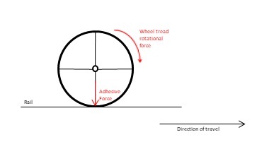
The Rotational force is determined by the force applied by the locomotive to turn the wheels, whilst the Adhesive force is determined by combining the weight on the drive wheels and the adhesion of the wheels to the track. Both of these parameters vary with time and the locomotive postion on the track, this produces a certain amount of wheel slip. The wheel slip speed is the difference between the speed of the train and the rotational speed of the wheel. Typically the wheel will rotate at a speed slightly faster then the train speed. The diagram below demonstrates the variation of wheel adhesion with variations in wheel slip.
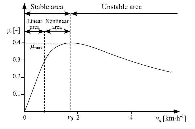
As can be seen from the diagram the resulting curve is split into three different areas,
- Linear Area - in the "Stable" area were wheel adhesion is linear compared to the slip velocity.
- Non-Linear Area - were wheel adhesion is non-linear compared to the slip velocity.
- Unstable Area - were wheel slip velocity is exceeded and slip starts to occur. The unstable area typically might occur once wheel slip exceeds 2km/h.
The wheel adhesion will never exceed the maximum Coefficient of Friction between the rails and the wheels (sometimes called rail resistance) which is determined by the track conditions. Typically, for steel on steel contact, such as a railway wheel the coefficient of friction for dry rails is between 0.35 and 0.5, whereas it can fall to a value of 0.05 in extreme conditions such as freezing, wet weather or oil covered tracks, etc. Thus whilst a locomotive may start without any problems in dry weather, it may suffer slippage problems in wet or cold weather.
Normally the Rotational force required to start slipping is greater than the force required to maintain the slippage, this is due to the fact that once slipping has started the coefficient of friction changes from the static value to a dynamic value. The dynamic value of friction, which occurs when the wheel slips, is determined by the value in above diagram at high values of wheel slip. Thus to stop a slip once it occurs, the Rotational force will need to be reduced to a value less than the Adhesive force due to the wheel slip (reduced CoF). Typically this means closing the regulator until slipping ceases.
Most steam locomotive designers worked to a design principle of ensuring that the Factor of Adhesion (FoA) was between 4.0 and 5.0, to reduce the risk of locomotive slip. The FoA was defined as:
FoA = weight on the drive wheels / starting tractive effort.
Diesel and electric locomotives can work with a much lower factor of adhesion than a reciprocating steam locomotive because their power is applied smoothly, unlike the pulsed force application of the steam locomotive. The pulses can, to some extent, be smoothed in a steam locomotive by fitting 3 cylinders or 4 cylinders. A 4-cylinder engine with cranks at 180 degrees will deliver similar pulses to a 2-cylinder engine. Alternatively, a geared steam locomotive can deliver a smooth torque similar to that of a diesel or electric locomotive.
Thus it can be seen, there is a balance between the weight on the drive wheels, and the amount of tractive effort that the locomotive can utilise. For example, a light weight locomotive would not be able to use as much tractive force to pull its load as a heavier locomotive, and thus the load that the locomotive can pull will be less.
The main parameters influencing slip on the locomotive are:
- Drive Wheel Weight - the weight on the drive wheels is one of the main contributing factor for the locomotive's adhesion.
- Coefficient of Friction - changes with weather or track conditions. Wet or icy weather can reduce the rail resistance, thus increasing the risk of slipping. Even leaves on the track can significantly reduce the friction coefficient, and contribute to a slippage occuring. Train loads were often reduced in snow and ice conditions to reduce the risk of slip.
- Tractive Force - the amount of tractive force required to start, and maintain the speed of the train. This force can produce excessive forces on the wheels and cause slippage.
Rotational Force
Diesel or Electric Locomotive
A diesel or electric locomotive produces a constant force on the wheel for the complete rotation of the wheel, so it is reasonably straight forward to calculate the Rotational force and Adhesive force at any point around the wheel. This will determine whether slip is likely to occur.
Steam Locomotive
To understand the mechanism of adhesion and slippage on a steam locomotive we need to study the complete rotation of the drive wheel. As shown in the diagram below, we notice that it is connected to the steam cylinder by a series of rods via the crank pins on each wheel.
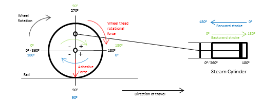
By studying a complete revolution of the wheel (i.e. 0o to 360o deg) in the diagram, we see that for each wheel revolution, the steam cylinder will do two strokes, i.e. one in the forward direction (green text), and one in the backward direction (blue text). Each of these strokes by the steam cylinder will either push or pull the wheel through part of its revolution. A force is exerted on the crank pin at the various angles of rotation by the wheel, the component of this force that acts "in line" with the wheel tread (i.e. Wheel Tread Rotational Force) is proportional to the angle of rotation. The Adhesive Force tends to resist the slipping effect created by the Wheel Tread Rotational Force.
Typically for a 2 cylinder simple locomotive the crank pins are positioned 90 deg apart on the wheels on either side of the locomotive. When steam is admitted to the steam cylinder the connecting rods push the crank pins (and the wheel). The intensity of the force created on the crank pins varies from instant to instant as the wheel rotates around, unlike a diesel or electric locomotive which have a constant force applied to the wheels during the full revolution. Thus the first force component contributing to the rotational force is the horizontal 'cranking' effort.
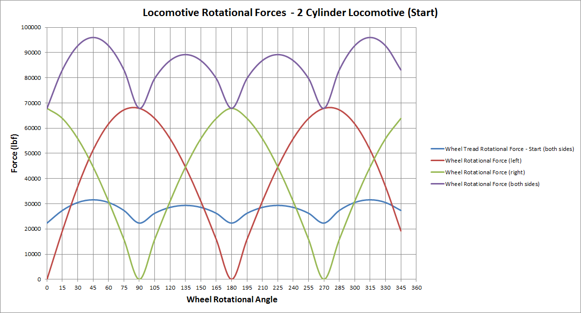
The "Locomotive Rotational Forces (Start)" diagram above shows the key forces acting on the wheel during a full wheel revolution when the locomotive first starts moving. The red curve shows the forces on the wheels on the left side of the locomotive. As can be seen, the force varies throughout the "forward" and "backward" stroke of the steam cylinder. Similarly for the forces on the right hand side wheels, which are shown in the green curve. To obtain the total force acting upon the drive wheels, the forces on either side of the locomotive need to be summed together. The purple curve represents the summated rotational forces on the wheel of the locomotive. The final step is to find the force component acting upon the tread of the wheel (Wheel Tread Rotational Force). The ligh blue curve depicts this component. Thus it can be seen that during a single revolution of the drive wheels on a steam locomotive the wheel force has four (4) maximum values, and four (4) minimum values, and varies depending upon the angle of rotation (or position of the crank pin).
At start, the inertia of the connecting rods and reciprocating parts are assumed to be negligible, and the pressure in the steam cylinder is assumed to be a maximum (i.e. maximum cutoff and regulator). However as the locomotive speed, and hence the wheel rotation, increases the inertia becomes more significant, and the pressure in the steam cylinder will vary throughout the stroke. For more information on how the pressure varies throughout the cylinder stroke refer to the Steam Cylinder Indicator Diagrams.
The inertia applied by the crank tends to assist the rotation of the wheel (add to the rotational force) in some quadrants of the wheels rotation, and to oppose the rotation of the wheel (subtract from the rotational force). This is indicated on the above diagram of the wheel by the '+' or '-' syymbols in the different quadrients of the diagram.
The final component is the impact of the inertia of the connecting rods as they move through the various positions as the wheel rotates. This inertia varies as the locomotive speed increases. Typically the correct position of weights ('balancing') on the connecting rods can mitigate the impact of the inertia on the rotational force. As stated, typically this component is not taken into account at the point of the locomotive starting.
We can calculate and add these different components together to end up with a series of curves for different speeds, as shown below, that increase and decrease as the wheel rotates.
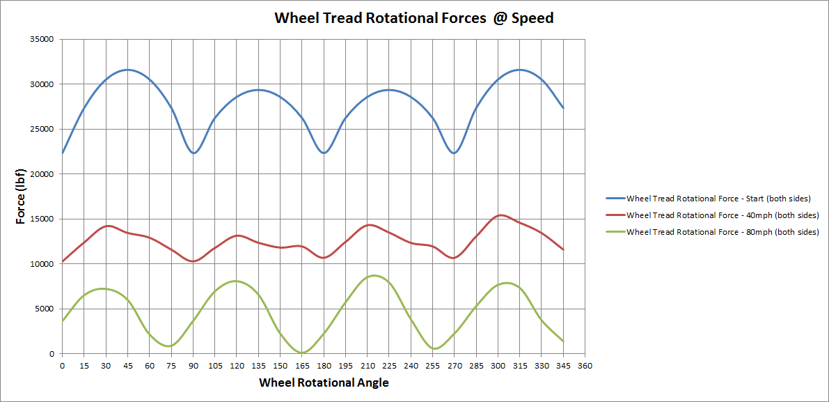
The diagram above shows that the Wheel Tread Rotational Force tends to decrease as the speed of the locomotive increases, due to the decreasing pressures in the steam cylinder, and the increasing impact of the inertia of the rods and reciprocating gears.
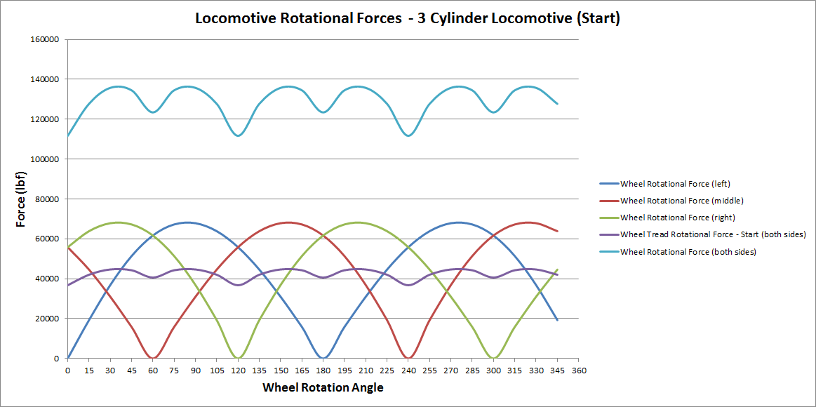
So far the discussion above has focused on 2 cylinder locomotives, however the same principles apply to 3 cylinder locomotives as well. The only difference is that the three crank positions for each of the cylinders is 120o deg apart, compared with the 90o deg separation of the 2 cylinder locomotive. The diagram below shows the shape of the rotational forces for a 3 cylinder locomotive, and demonstrates the 'smoother' Wheel Tread Rotational Force due to the 3 cylinders.
Adhesive Force
Opposed to the rotating forces, which we have found to vary widely throughout a complete revolution, is the Adhesive Force. The following factors determine the adhesive force and therefore the resistance to slipping at any instant. The first two are independent of speed and the third is effective only at high speed.
- The static or dead load on drivers.
- The vertical thrust on the crank pin, remembering it is always positive when the locomotive is running forward and negative when running in reverse.
- The vertical effect of the excess balance for the rotating parts of the connecting rods and reciprocating gear.
The algebraic sum of the above three items for any position, multiplied by the coefficient of rail-friction gives the resistance to slipping, and ideally this product should be greater than the rotative effort for any crank position to ensure that the locomotive wheels do not start slipping.
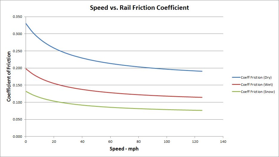
In the 1950s, through experimentation, Curtius - Kniffler postulated that the Coefficient of Friction varied with speed. They developed the following empirical formula to fit with the test results, and describe the behaviour of friction as the speed varies.
Friction on Dry track:
μdry = ( 7.5 / ( v + 44 ) ) + 0.161
Friction on Wet track:
μwet = ( 7.5 / ( v + 44 ) ) + 0.13
where -
v = speed in km/h.
Over the years various experiments have been undertaken which have seen some suggested changes to these formula, and the values contained within them. One change has been to add a correction factor that is applied to the output of each of the above formulas.
The Curtius - Kniffler formula is graphed in the diagram below to show the variation of friction with speed.
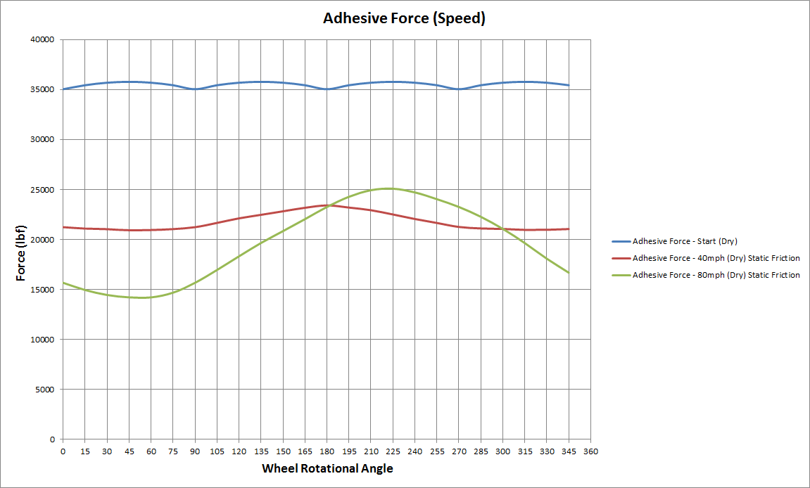
The diagram below combines all of the above elements together to show the variation of the Adhesive Force as the steam locomotive travels at different speeds.
The Coefficient of Friction for a locomotive can be can be calculated by the following formula with Adhesion Coefficient often being expressed as a percentage:
where -
DriveForce = Maximum Drive Force on Wheels (N or lbf).
DrvWheel = Weight on Drive Wheels (kg or lbs)
Wheel Slip
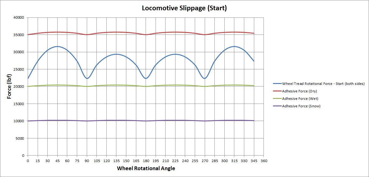
If the Wheel Tread Rotational Force and the Adhesive Force are now compared, it is possible to make a determination as to whether the locomotive will suffer from slippage or not. Using the steam locomotive as a guide, and refering to the diagram below, the starting Wheel Tread Rotational Force (at full reverser, and regulator settings) is graphed against the Adhesive Forces for dry, wet, and snow covered rail conditions. Thus it can be seen that it is very unlikely that slippage will occur on dry rails as the Adhesive Force is greater then the Wheel Tread Rotational Force. However the Adhesive Force for wet and snowy conditions is less then the Wheel Tread Rotational Force, and therefore slip is likely to occur. It should be noted that the Wheel Tread Rotational Force has been calculated on the assumption that the regulator is fully open, and full steam pressure is applied to the steam cylinder. This force could be reduced if the regulator was only partially open, and the steam pressure reduced.
It should also be noted that slippage may occur even if the Wheel Tread Rotational Force exceeds the Adhesive Force for only part of the wheel rotation, as the Adhesive Force will be significantly reduced due to the reduction in the friction between the wheel and rails (as shown in the following diagram) if the wheel starts to slip. This is due to the dynamic (or kinetic friction, when wheel slip occurs) coeficient of friction being significiantly less then the static (when wheel is rotating in the stable slip area) coefficient of friction.
As can be seen in this diagram, the Wheel Tread Rotational Force can be increased until the point that it exceeds the Adhesive Force, at which point, to control the slippage it will be necessary to close the regulator (i.e. reduce steam pressure, and hence tractive force) until the Wheel Tread Rotational Force is less then the Adhesive Force (due to kinetic coefficient), and the wheel slip stops. The regulator can then be slowly opened again, and thus slowly increase the speed of the locomotive. The use of a friction increaser, such as the application of sand to the track, can also be used to assist with overcoming slip. Sand application will be required until the Wheel Tread Rotational Force is less then the Adhesive force due to the static friction coefficient.
Thus in summary, to control slippage, as a general principal, either reduce the tractive force or increase the co-efficient of friction. Reducing the train load in snowy conditions will also assist in reducing the tractive force required to move the train.As the Wheel Tread Rotational Force has a series of maximum and minimum points, it is not necessary to calculate all of the differnt points on the curve to determine slip characteristics. Instead, a representative view can be determined by selecting the maximum point values, such as at 45o, 135o, 225o, or 315o for a 2 cylinder locomotive.
For a more detailed explanation of steam locomotive slippage refer to pg 276 of George Hendersons book, Locomotive Operation, a Technical and Practical Analysis.
OR Implementation
A steam adhesion model has been implemented into Open Rails based upon the principles and formula used to define the forces described in the above sections. To ustilise the adhesion model, the following options need to be selected in the Options Menu:
- Advanced adhesion model (Simulation TAB) - note that the moving average filter size does not apply in the steam adhesion model.
- Adhesion factor correction (Experimental TAB) - can be used to make the model less sensitive by adjusting the coefficient of friction value higher or lower. For accuracy of operation, it is recommended that a value of 100% be used (this sets the multiplication factor to 1), and thus this will ensure that the values are 'life like'.
- Adhesion factor random change (Experimental TAB) - can be used to add a level of random variation to the model, ie allows the friction coefficient value to change randomly rather then being set at a constant value. Increasing this value will increase the amount of random variation applied to the friction coefficient. A value of close to 1% will represent negligible random variation.
To facilitate accurate calculation of the Adhesive weight of the locomotive it is recommended that the Drive Wheel weight (
The HUD provides information about the current slip 'status' of the locomotive. A summary appears in the 'Forces Information" window, and more detailed information appears in the 'Steam Locomotive' window.
It should be noted that geared steam locomotives tend to behave more like diesel locomotives, i.e. with consistent rotational forces for a full revoultion of the drive wheel, therefore these types of locomotive use the same advanced adhesion model as diesel and electric locomotives.